How to repair MacBook Magsafe and Magsafe 2 chargers
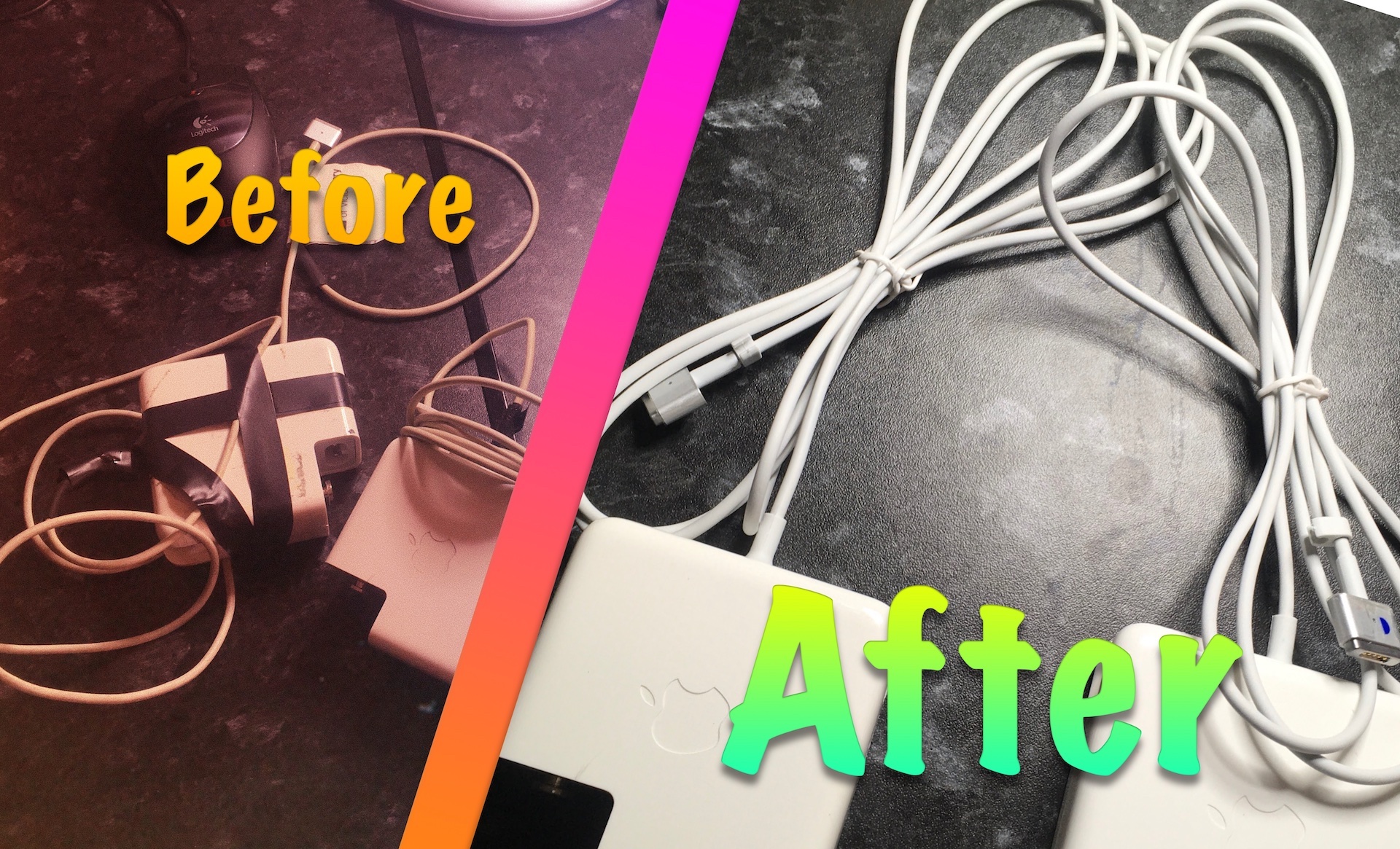
The flimsy and non-user replaceable cables found in the Magsafe 1 and 2 chargers are always the main point of failure. The new USB-C chargers have fixed this by making the cables removable to allow Apple to sell you one at 20€… but those of us using an older MacBook with a torn charger cable still have to shell out 80€ for a brand new one or, even worse, go for a cheap/fake eBay/Amazon counterpart for 1/4 of the cost.
There is a third alternative. Why not fix your current one and help save the planet by reducing e-Waste? Here is a complete guide to help you recover your MacBook’s MagSafe charger by replacing only the torn cable with a new one.
Why you should not buy a knockoff charger
Please do not buy one of these. If you do not think you are able to undertake this repair, please take it to a local repair shop and have them do it for you, or simply buy a genuine Apple charger.
Here are the main problems with knockoff chargers:
- Their cables are flimsier than the original (as if that were possible…)
- Manufacturers cut down on costs heavily, a.k.a. you really get what you pay for. Such chargers are much lighter, indicating the presence of less components, crude construction and no copper at all. In particular, the AC to DC conversion is performed using lower quality components, resulting in increased waste heat (inefficiency).
- Buzzing and static in the 3.5mm headphone jack. I once had one of these chargers and its bad grounding caused my laptop’s headphones to constantly buzz.
- Voltage fluctuations can lead to unexpected shutdowns when the system is under load.
- The so-called coil whine, where you hear buzzing or hissing sounds coming from the charger.
- Lower or no overcurrent protection, which can simply fry your computer when there is a thunder storm or a failure in the power grid.
- Electric shocks! Yes, with my now deceased fake eBay charger I got a shock in my ears if I wore metal headphones, like my Xiaomi Piston Headphones.
Parts
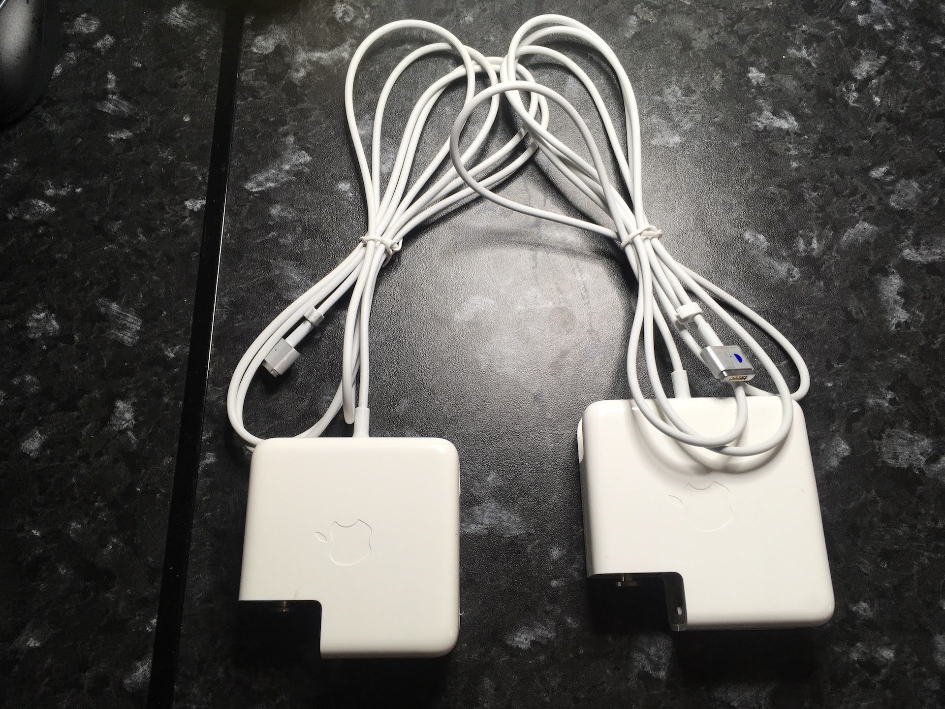
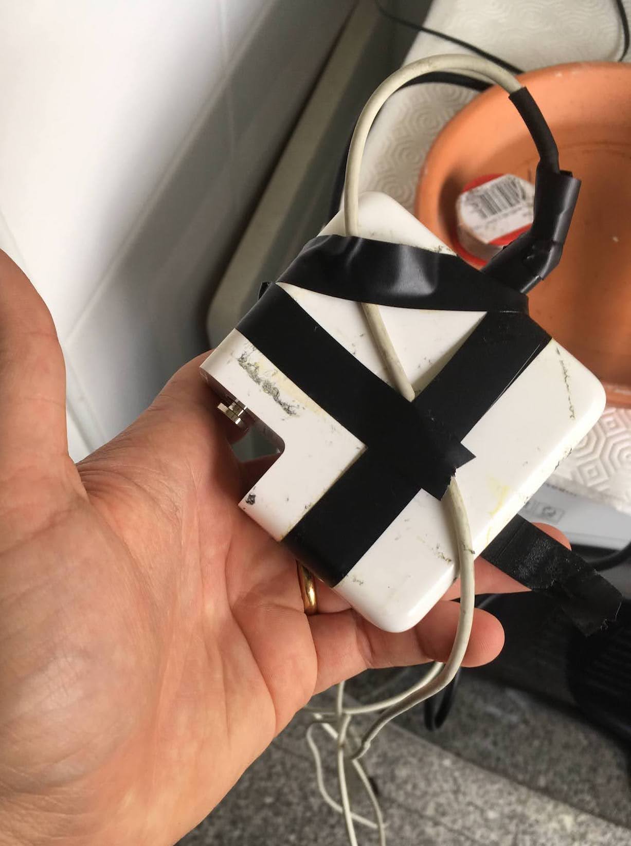 The charger that we will fix in this guide.
- Your broken MagSafe 1 or MagSafe 2 charger.
- A Magsafe 1 or Magsafe 2 replacement cable (Amazon link).
- Heat-shrinkable tubing for insulating the ends of the new cable (Amazon Link)
- A roll of 0.6mm solder wire. (Amazon Link)
- Temperature-resistant adhesive assembly glue, commonly used in house work as an alternative to screws and nails. I got one with approx. 80ºC max temperature, the one in the link should be even more resistant. (Amazon Link).
Tools
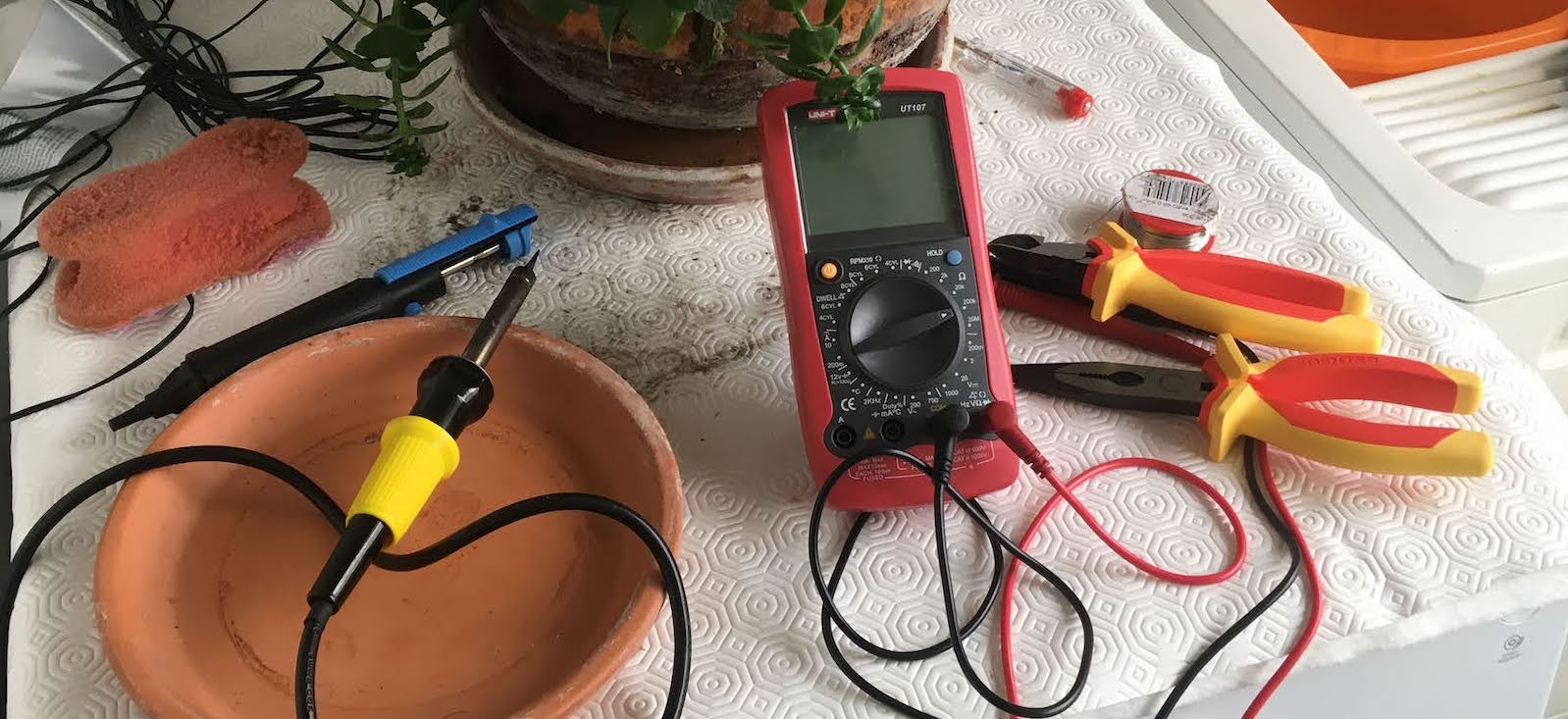 Tools necessary for replacing MacBook charger’s cable.
- Long-nosed pliers (Amazon Link).
- Flat head pliers (Amazon Link).
- Soldering iron (65W-100W) (Amazon Link).
- Universal gun for adhesive tubes (Amazon Link).
- Old wet sponge for cleaning soldering iron.
Optional Tools
- Desoldering pump, useful for pumping out the old solder when removing the broken cable. (Amazon Link).
- Multimeter, for checking for continuity between the 12V and Ground wires after you solder, making sure that you do not have a short circuit. (Amazon Link).
Procedure
Open up the old charger
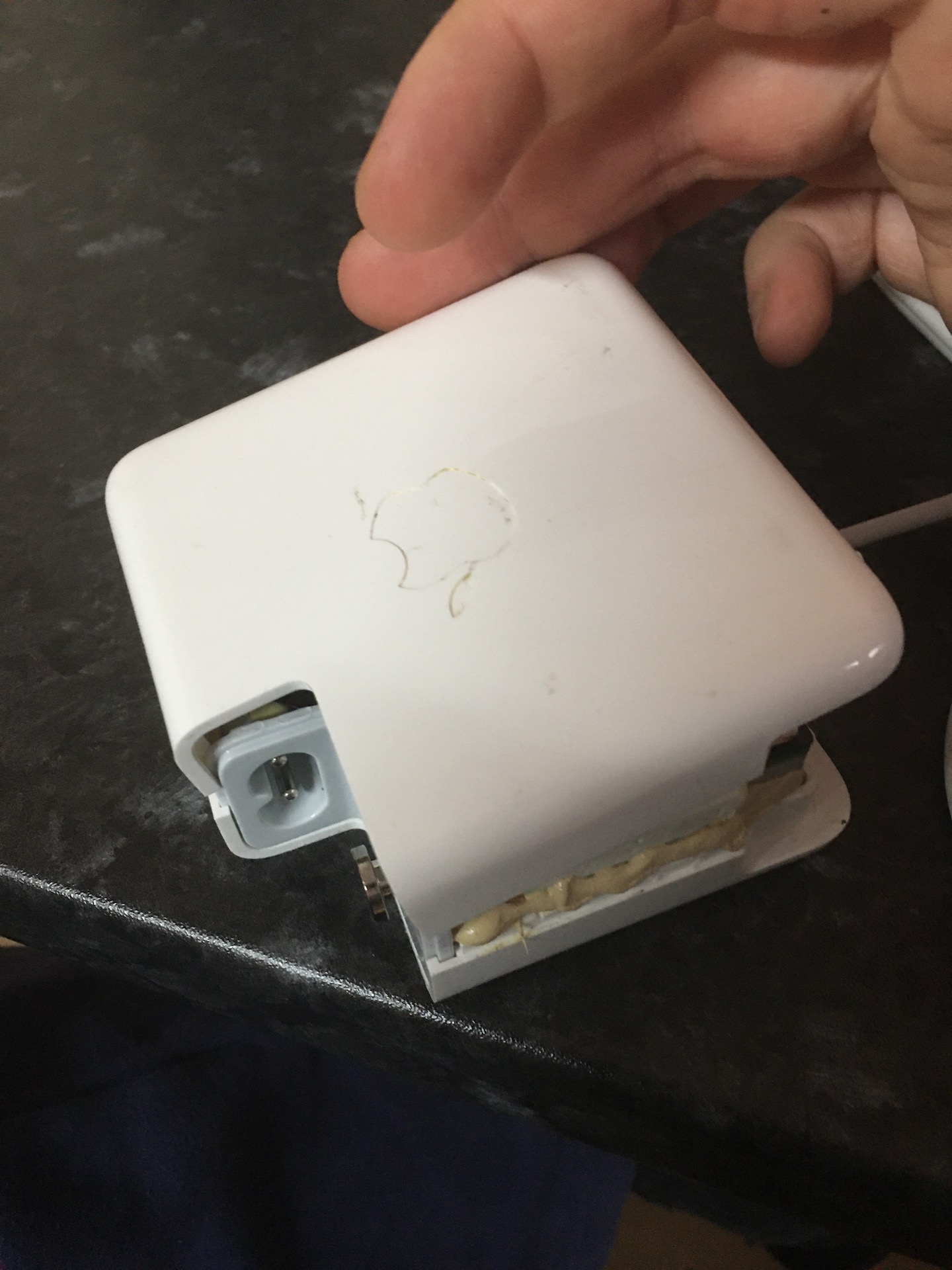
Position the tips of your flat head pliers on the edge of the charger where the folding clips for the wire are. Crack the charger open by exerting force on the pliers in the direction shown in the picture.
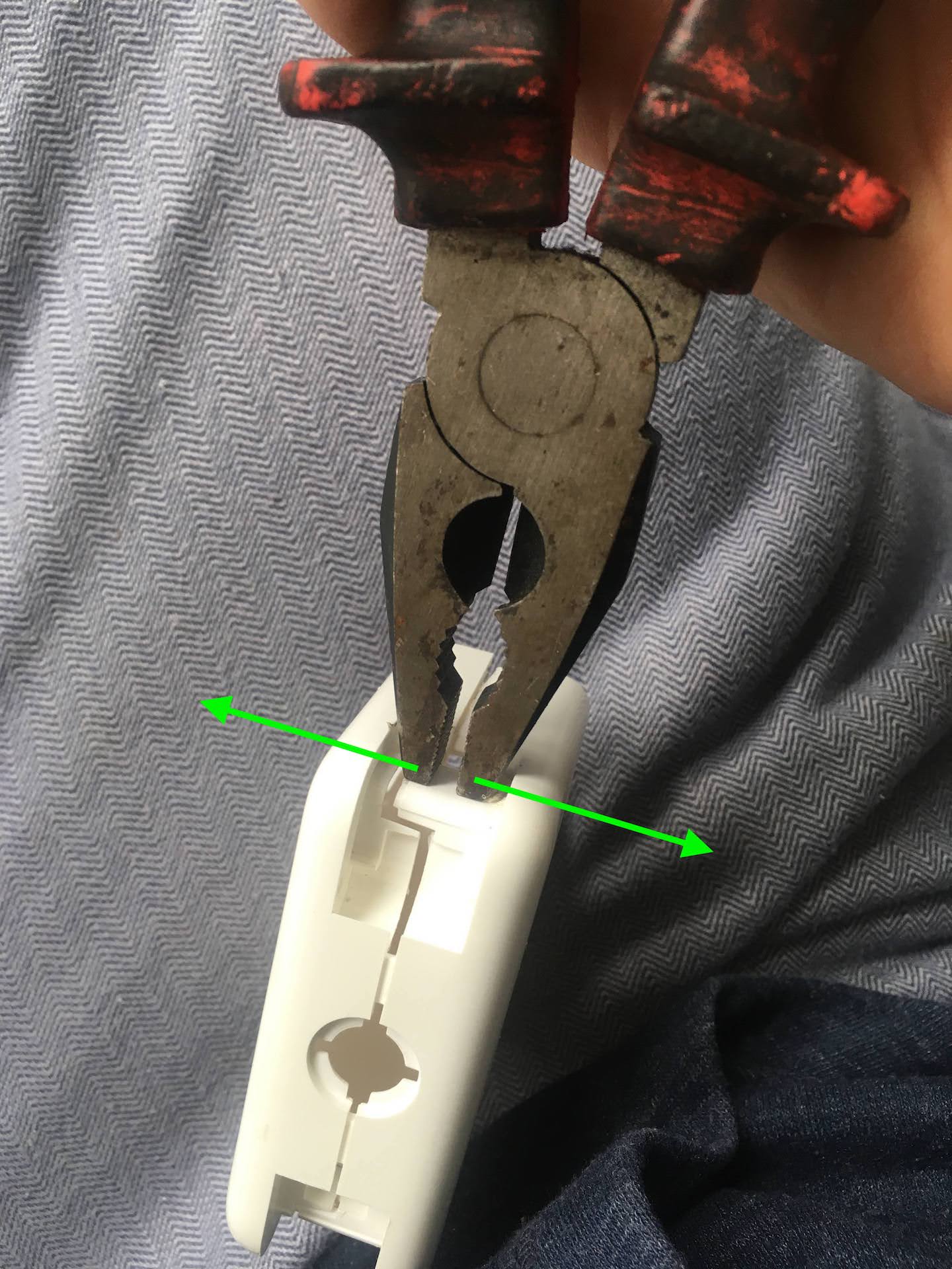 Using flat head pliers to open a MacBook Charger.
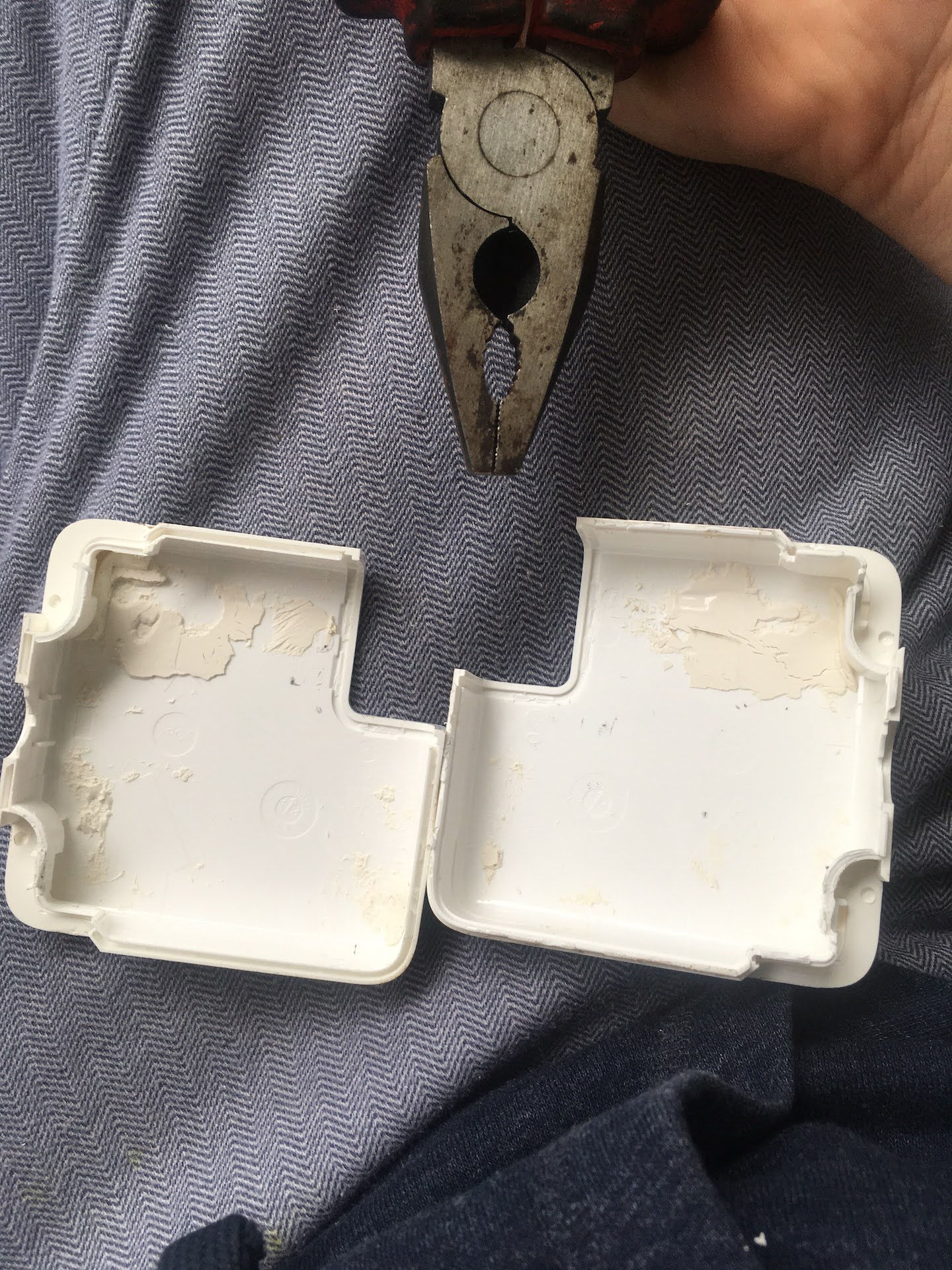 Using flat head pliers to open a MacBook Charger - Result.
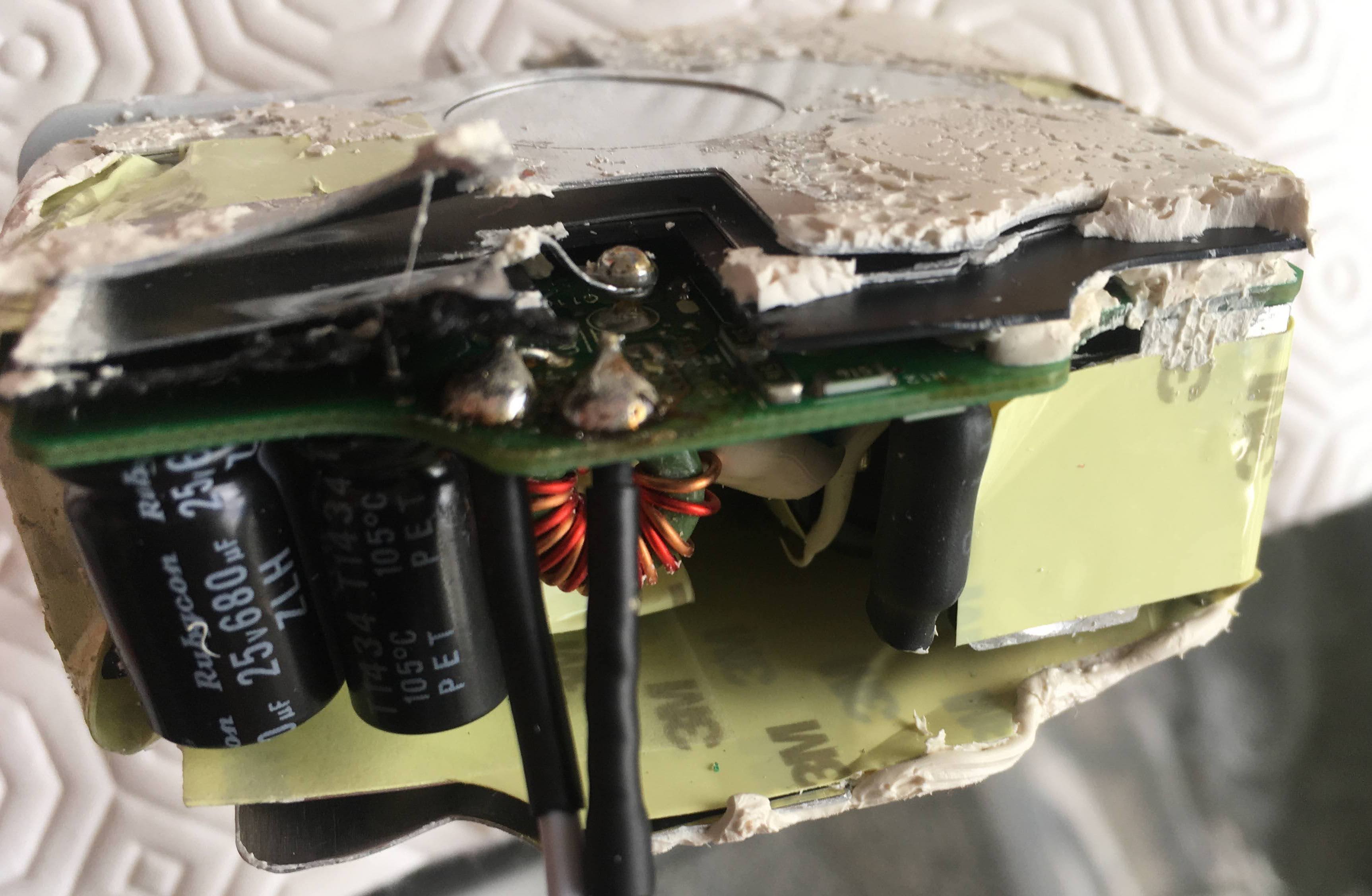
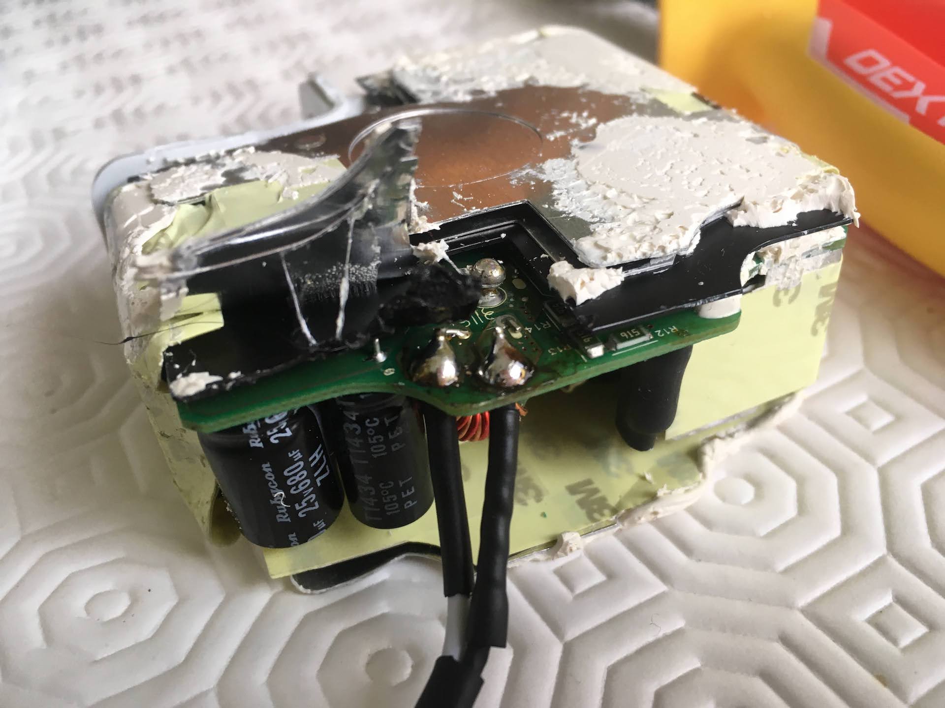
It takes some force as the interior cage of the charger is glued to the outside shell with some sort of high-power white adhesive.
Desoldering the old cable
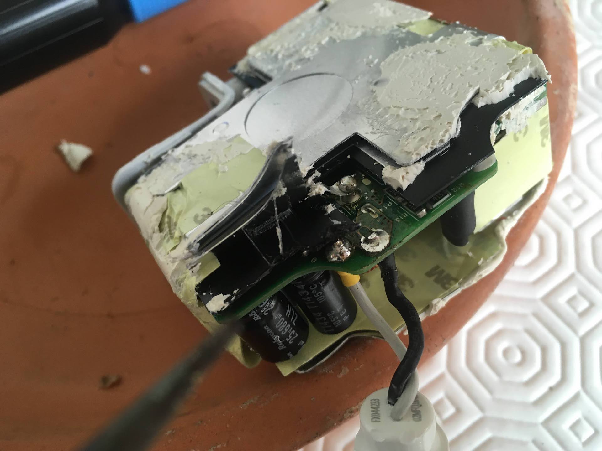
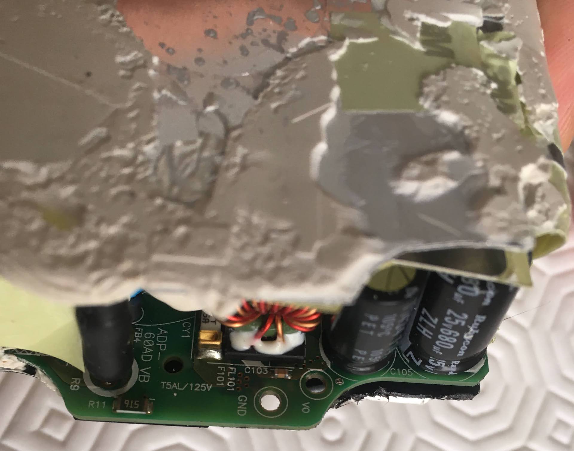
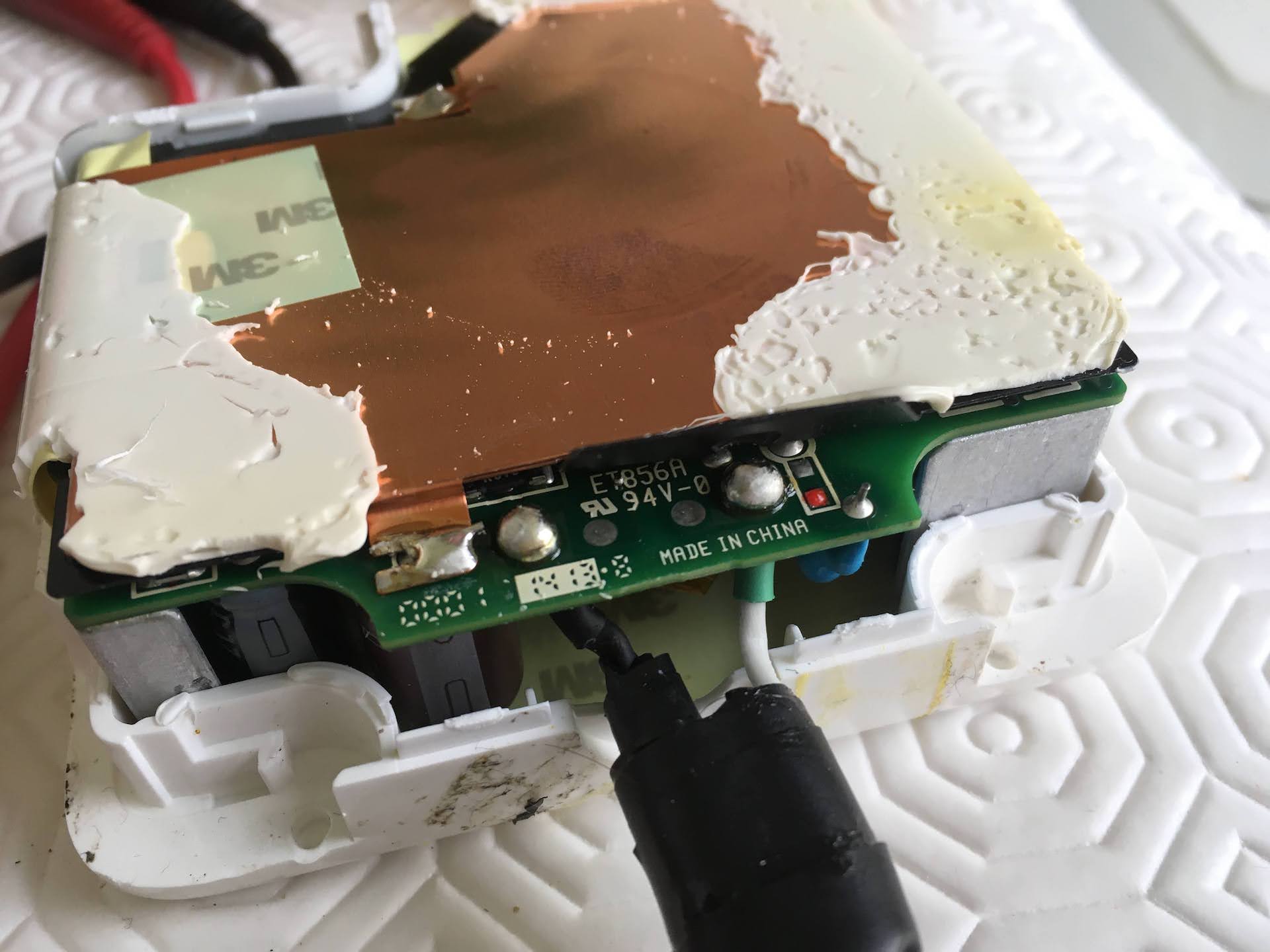
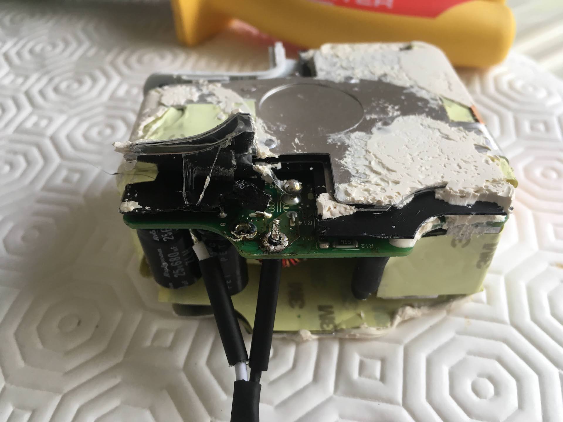
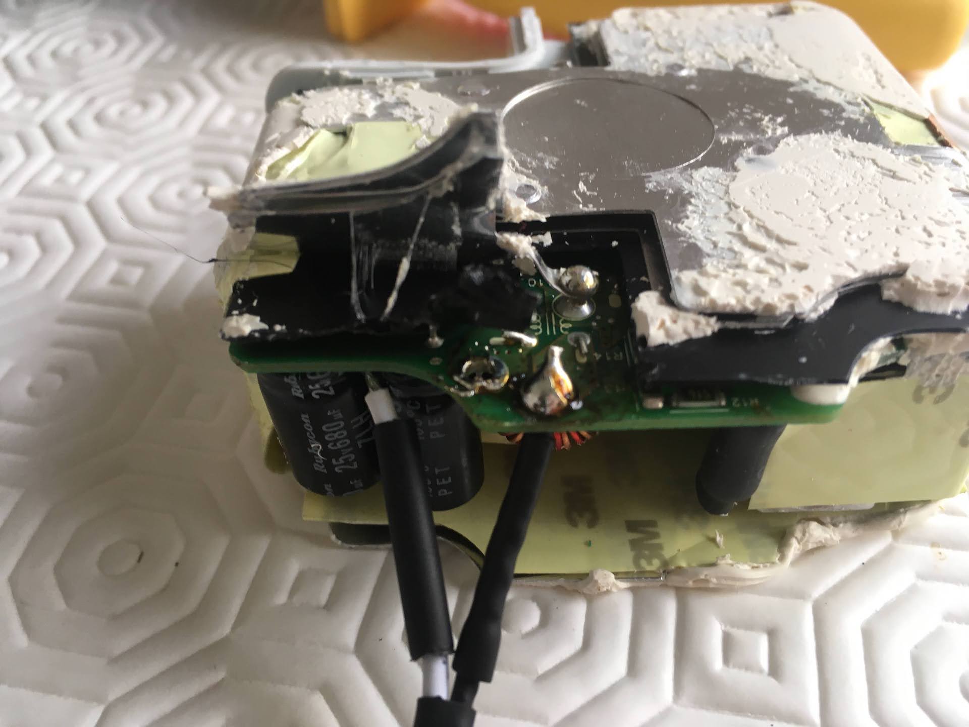
After cracking open the charger you will see that the cable is soldered to two large contacts.
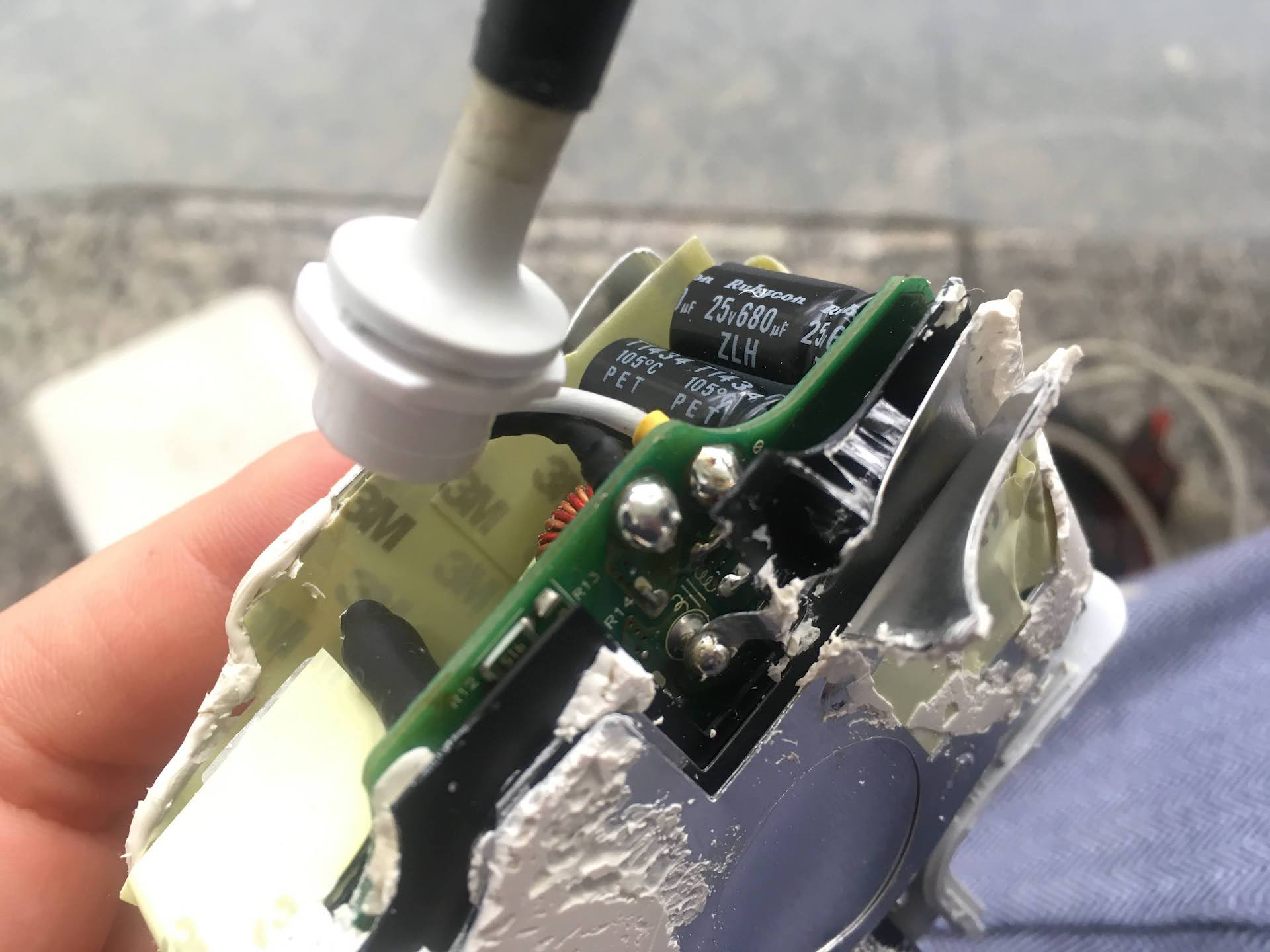
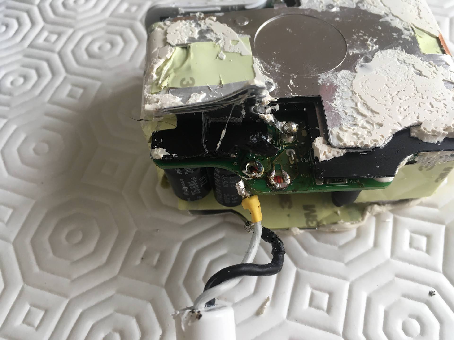
 GND and 12v contacts - detail of the contacts to desolder from the charger.
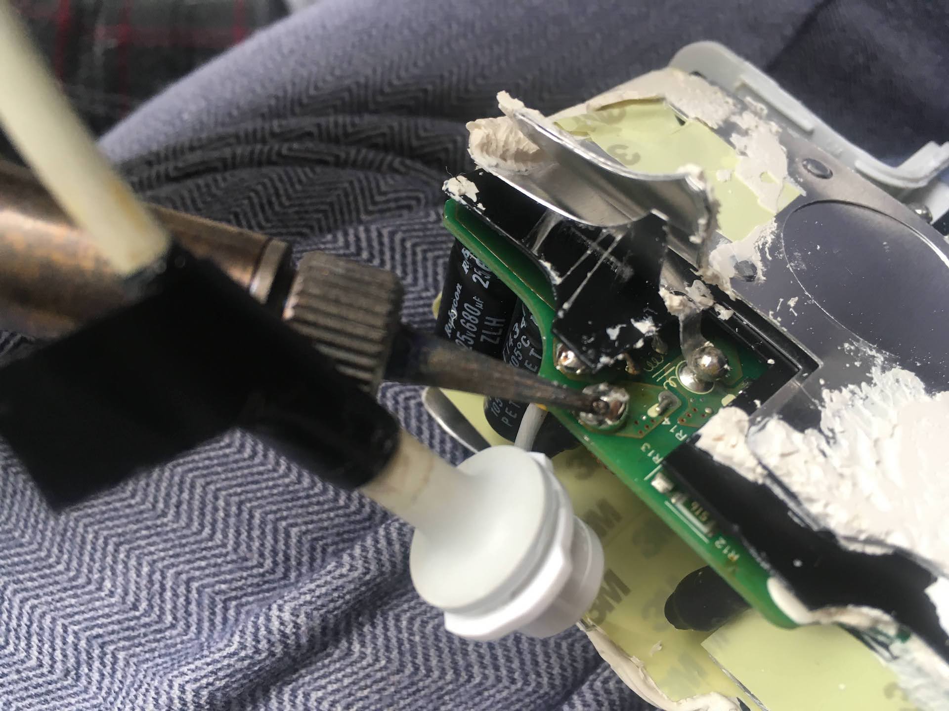
Time to desolder the old cable. I used a 65W soldering iron, which is quite weak for the purpose. The tip would not heat up the solder enough so I had to slide the iron across the contacts to supply enough heat. If you have a stronger soldering iron I recommend using that instead. Place it on a heat-resistant surface so that it does not burn through or melt anything while it is hot but not being used.
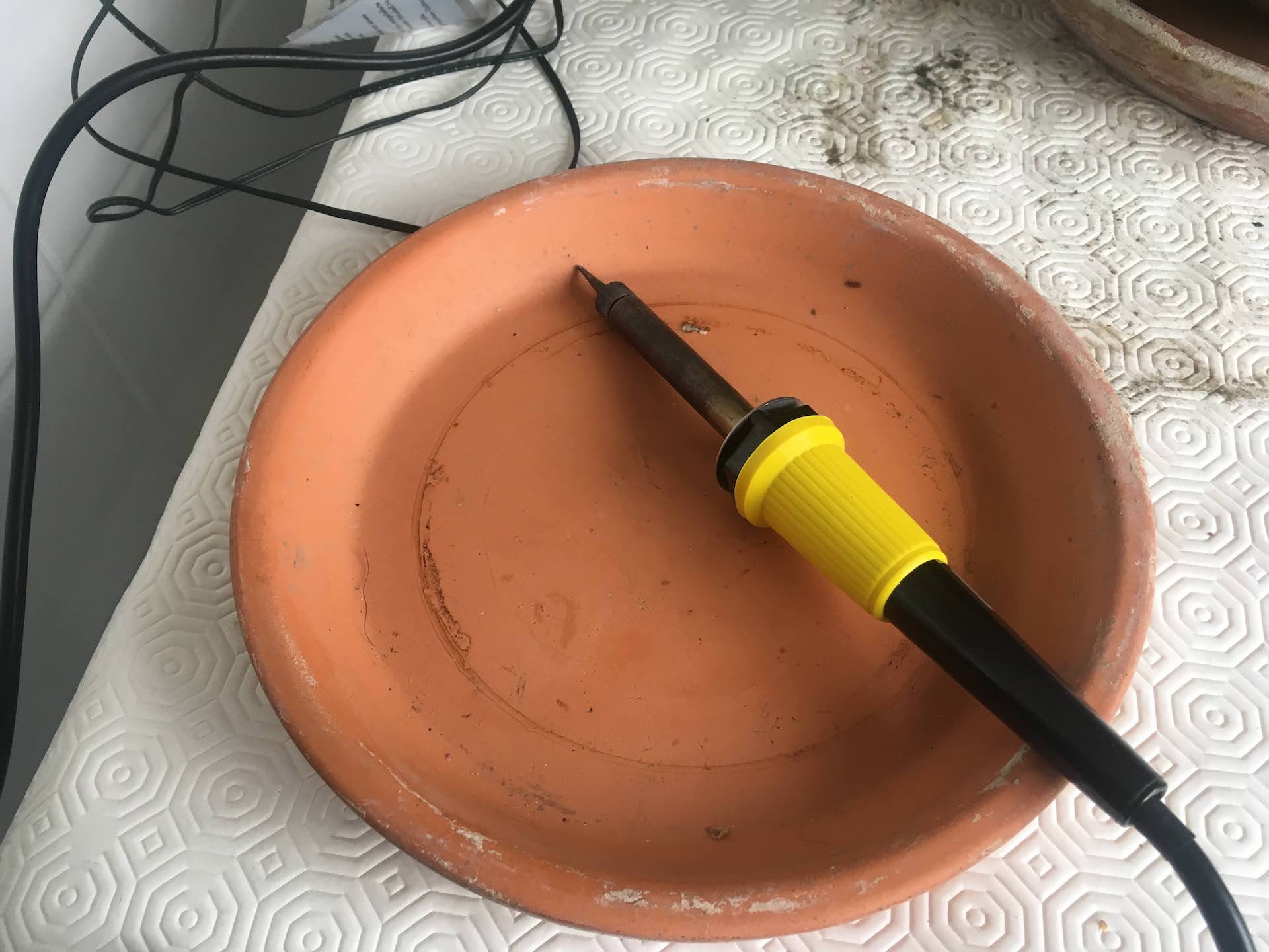 My 65W soldering iron.
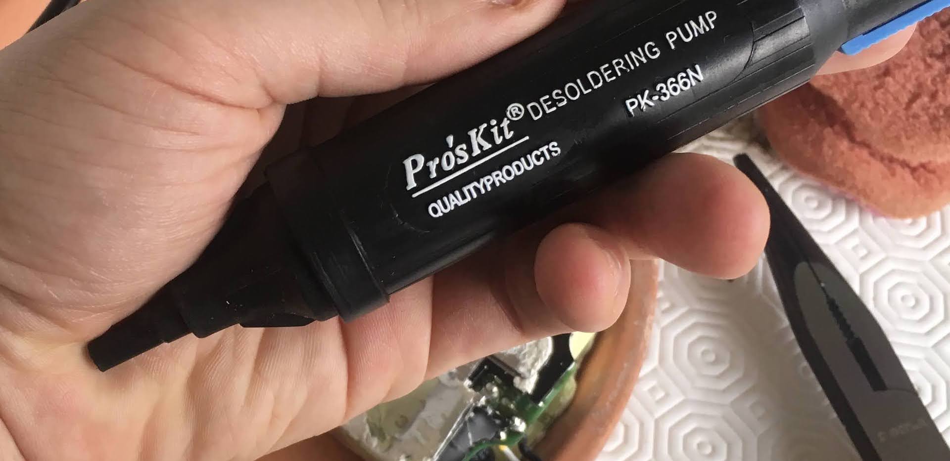 My desoldering pump.
If you have a desoldering pump, you can use it to pump out the solder as you liquify it with your soldering iron. Less solder in the contact will make it easier and easier to loosen the cable, especially when you use a weak soldering iron. A weak iron will have difficulty keeping the entire solder blob liquid, so the less solder the better when wiggling out the old cable.
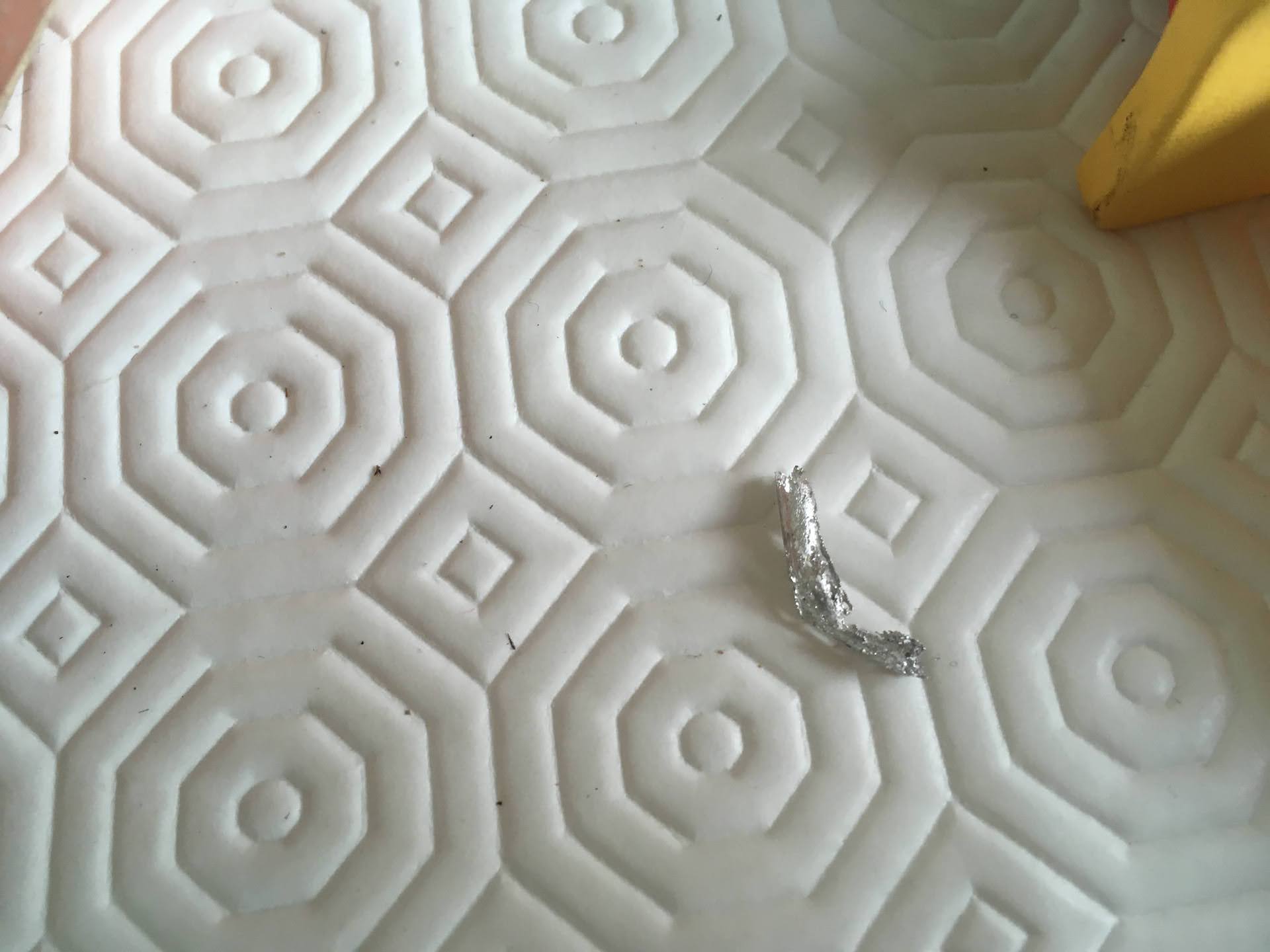
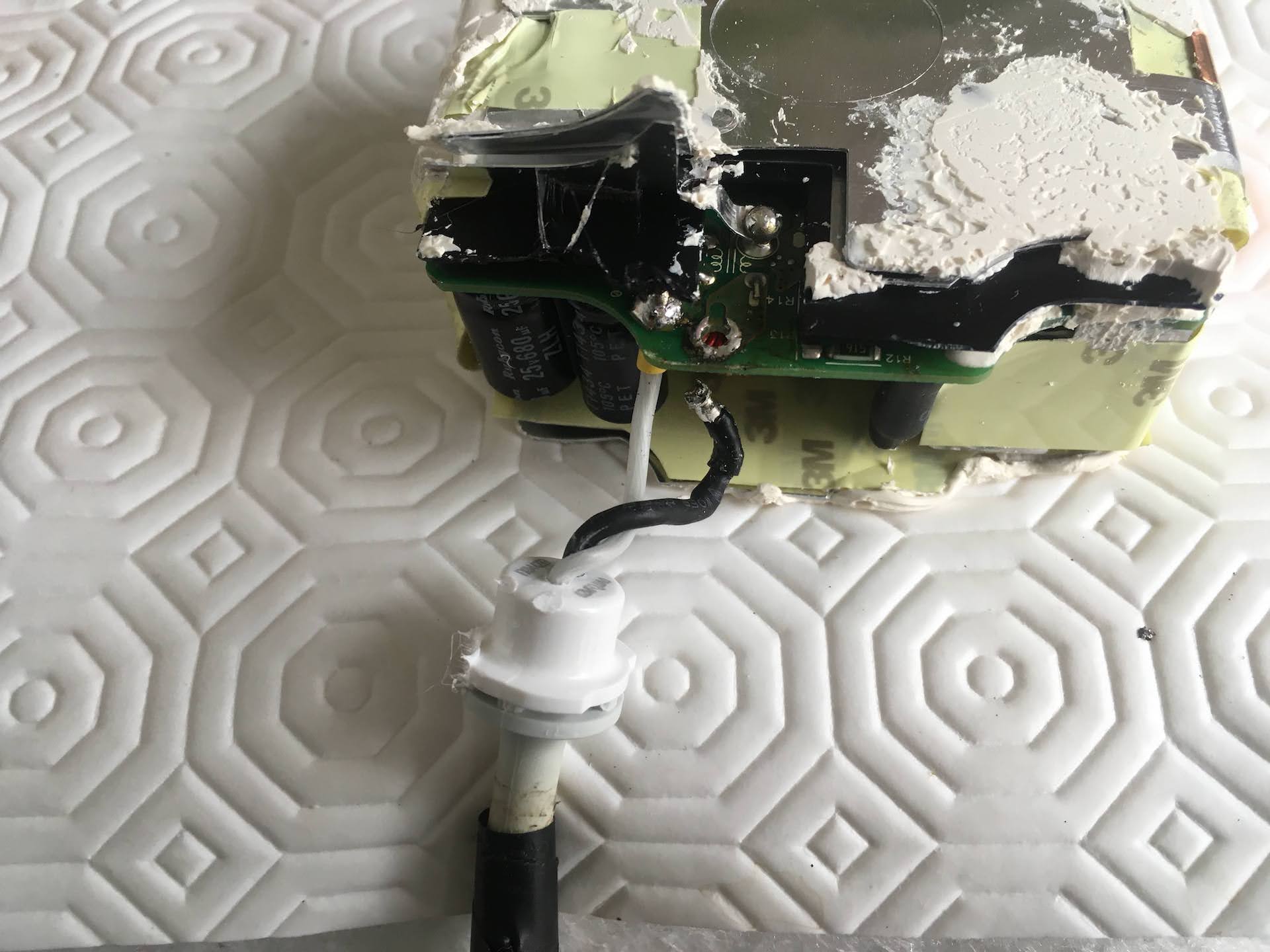
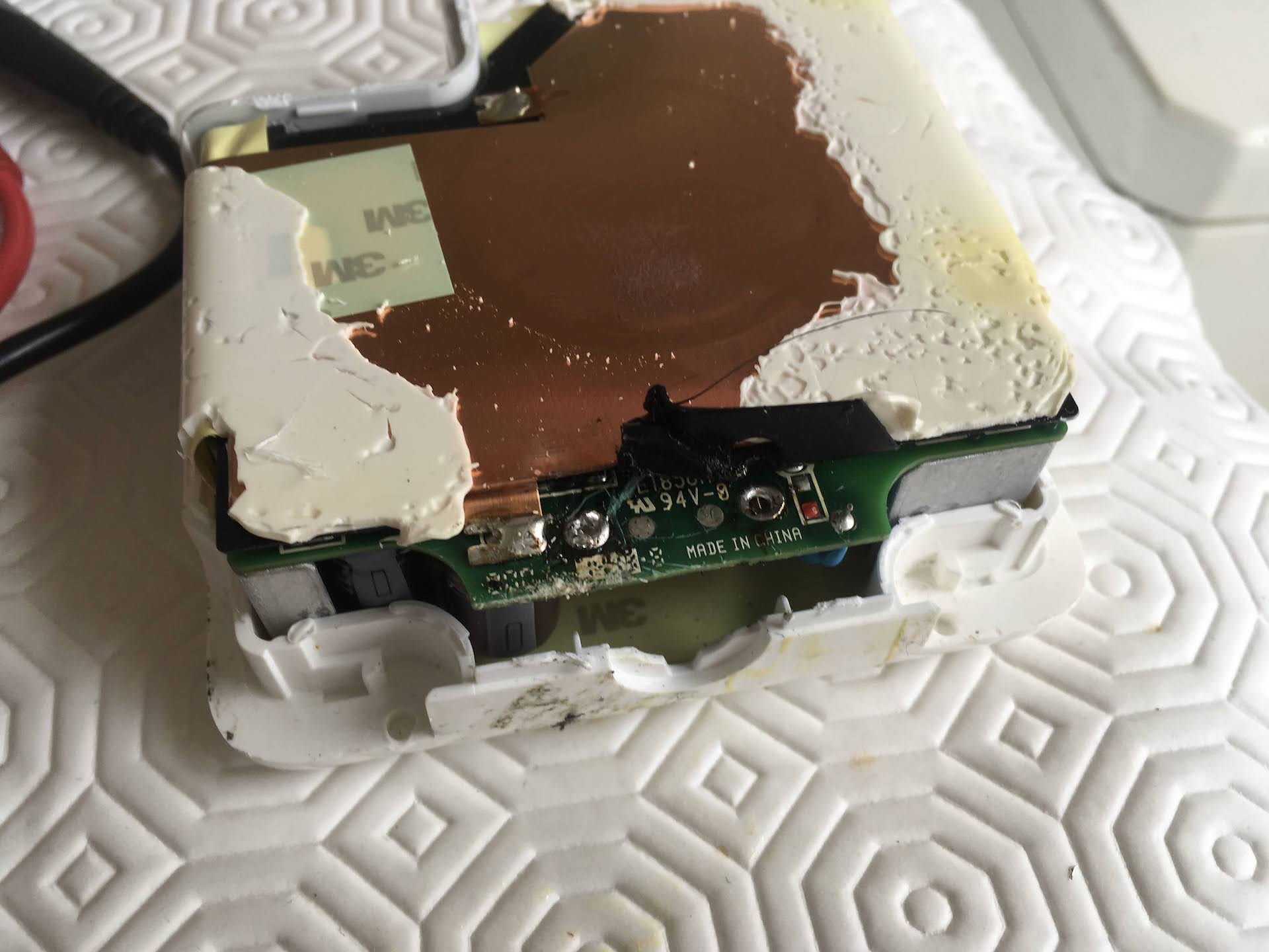
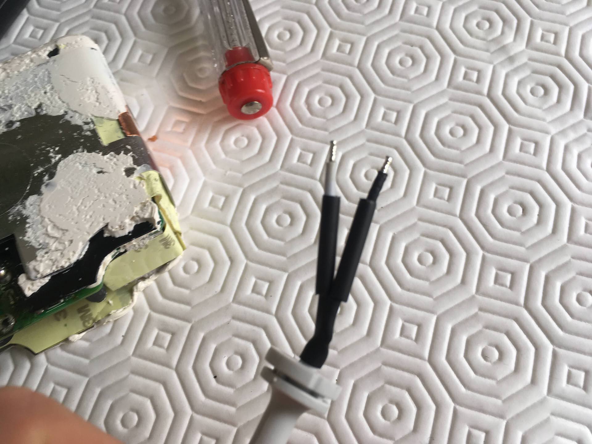
 Wire ends now free of solder blobs, after using the desoldering pump to suck out the excess solder.
After heating up the contacts and pumping out the excess solder, the large round solder blobs are gone and you can see the ends of the wire.
Using a desoldering pump is easy: You arm it, heat up your solder and trigger it close to the liquid solder. The spring will fire and quickly suck out the old solder. When you arm it again, the pumped solder, now solid, will come out from the desoldering pump’s nose.
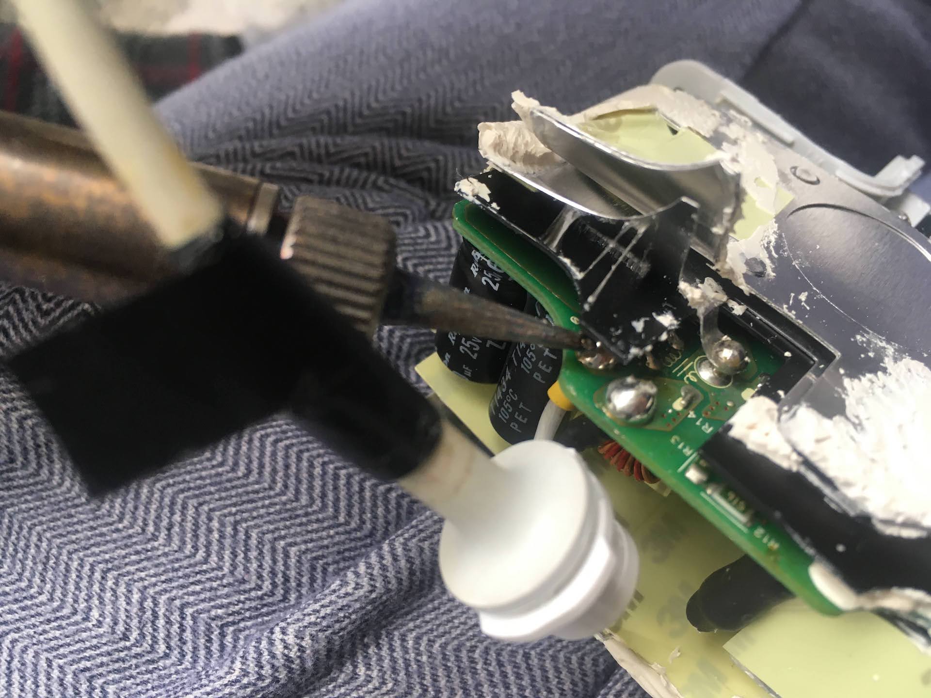
Now let’s start pulling out the cables while applying heat with the soldering iron. Use your thin-nosed pliers to apply some force to the wire while you heat up the contacts on the other end using your soldering iron. Try to apply the least amount of force to the wire until you see the solder liquify on the other side, otherwise you risk ripping the cable out altogether or to damage the circuit board.
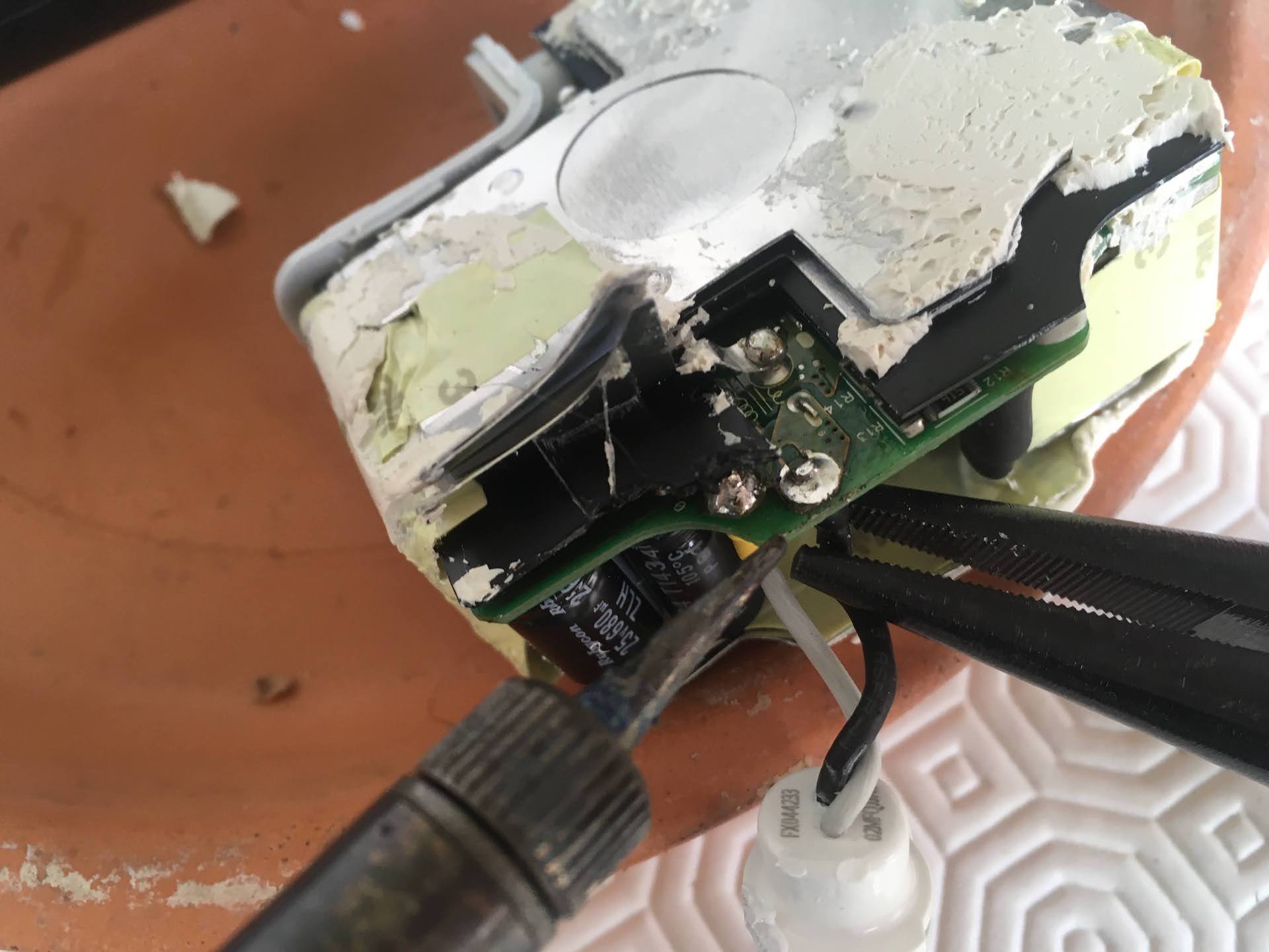
 Desoldering wires out of the circuit board.
Here is the same result for an 85W Charger (MacBook Pro 15 inch):
 The same result in a 15-inch MacBook charger
Prepare new cable with heat-shrinkable insulation sleeve
Add some heat-shrinkable tube to the ends of the new cable. This is a special type of plastic insulation that will retract when it is heated, forming an insulating layer over an exposed wire.
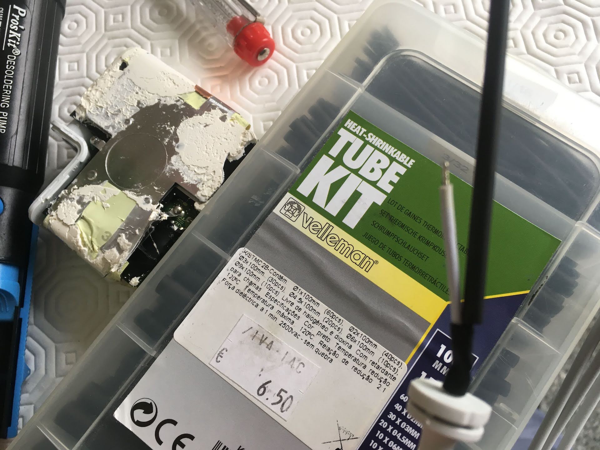 Box of heat shrinkable tubing for wire insulation (in multiple sizes).
Cut two pieces of insulation sleeve, roughly around 1 centimeters each.
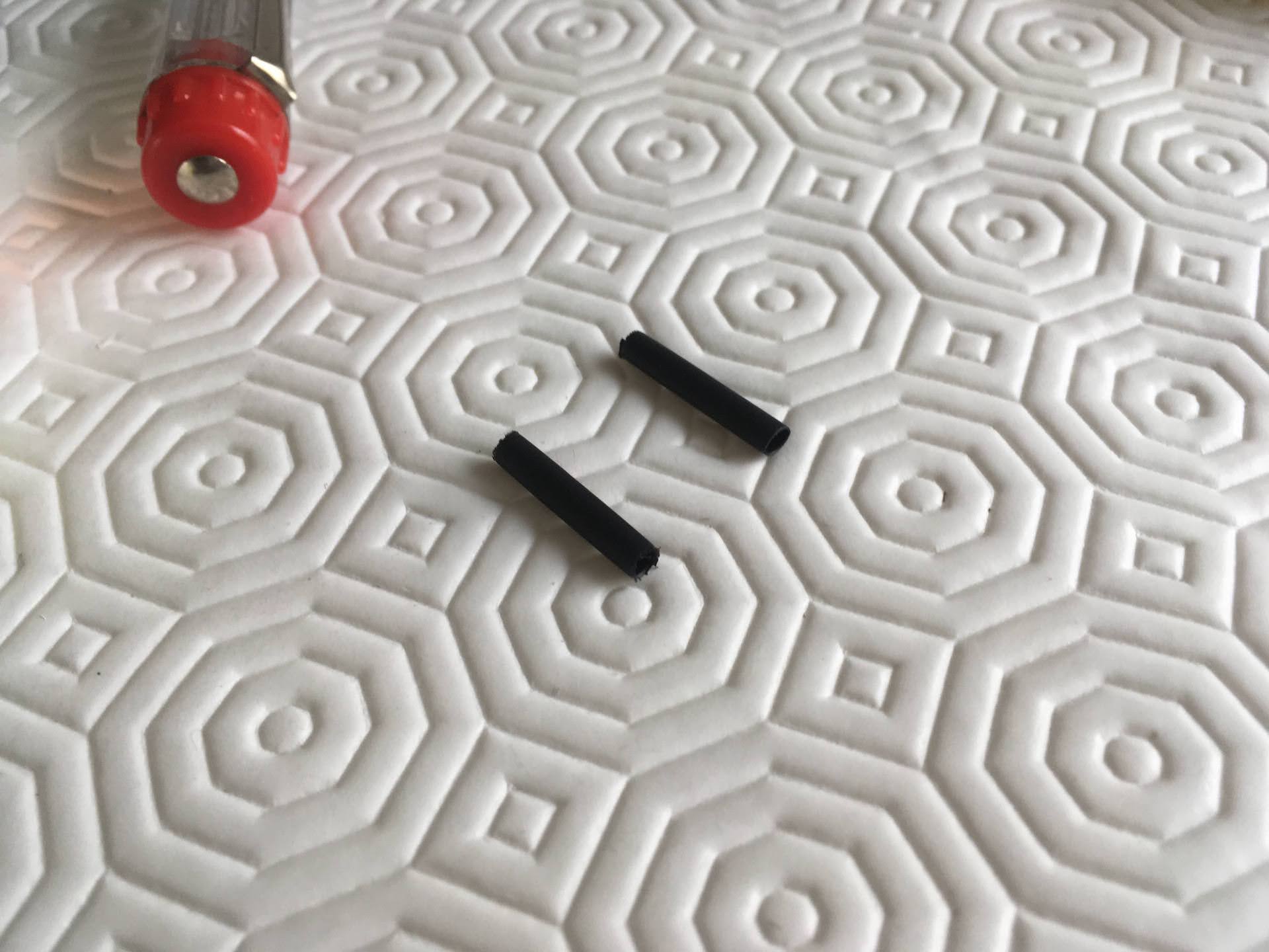 Insulation tubing now cut to size, around 1 centimeter will be enough.
Run one tube into each wire and you will be ready to start soldering. Normally you need to heat up the sleeve using a lighter or a candle, but in this case the residual heat of the soldering iron turned out to be sufficient. The sleeve will shrink as you solder.
Insulation tubing now placed into the wires, ready to solder.
Solder the new wires
Recall the picture you took before showing the colors of the wires in each hole of the charger’s circuit board. Run the same color wires into each hole.
 Wires placed into the holes of the charger circuit board.
Solder the two wires using your soldering iron. I recomment heating up the wire and then applying solder to the wire. The heat will be transmitted to the board and make the solder flow around each hole, as the metal in the board will heat up almost instantly when compared to the thick wire.
 One wire, already soldered….
 …and the second wire as well.
Test the charger
Use your multimeter to check for continuity between the two terminals. This is to make sure that you did not solder them together, creating a dangerous short-circuit!
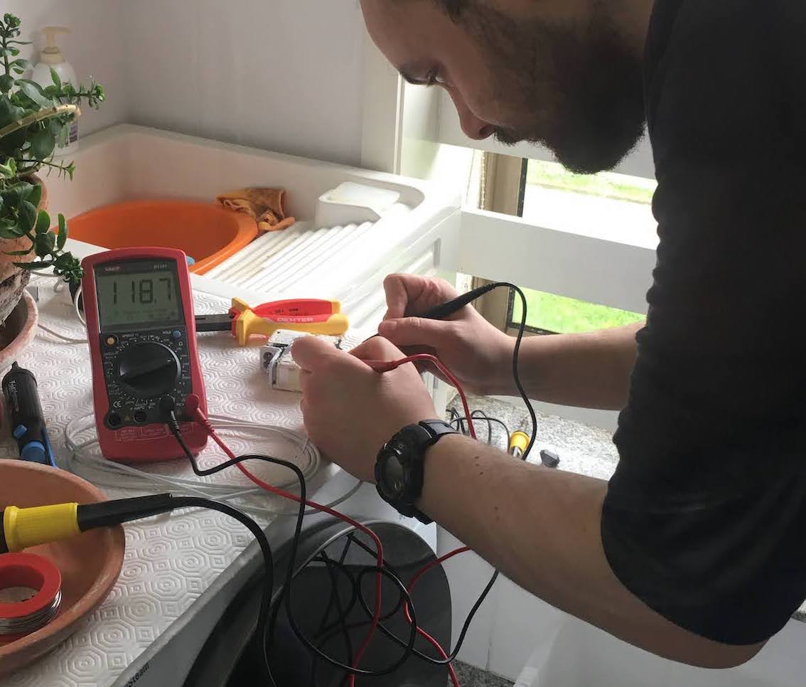 Testing for continuity.
If you get around 178 kΩ, that is fine. 0Ω means a short circuit!
 Finished result. Wires soldered and insulation covers the ends.
Re-sealing the charger
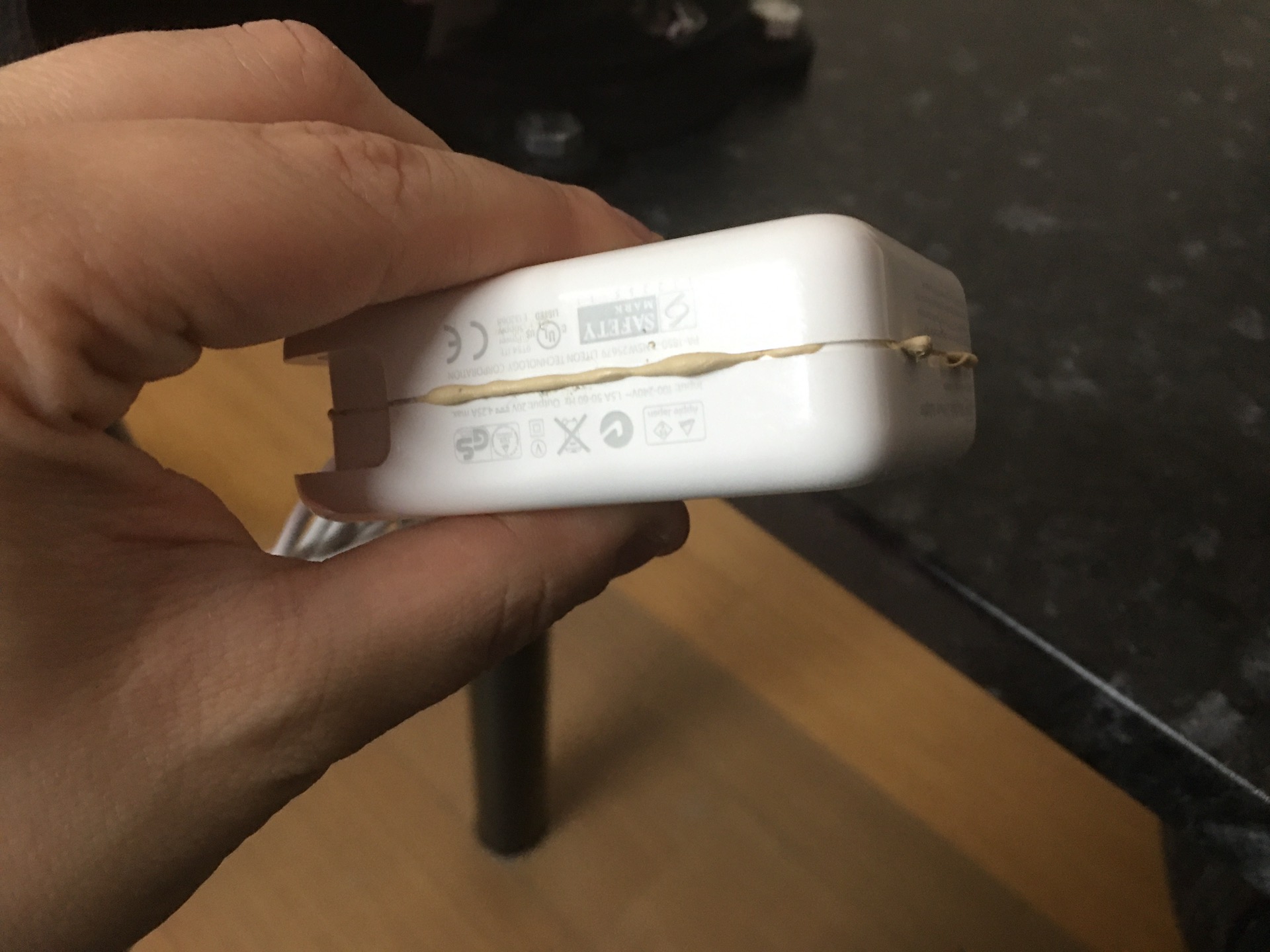
Get some high-temperature assembly adhesive and and coat the interior of the two halves of the charger. I used this high-strength glue that i found at a local supermarket chain. As long as it is resistant to temperature you should be good to go. If you find white adhesive instead of my off-white color may even get a better finish.
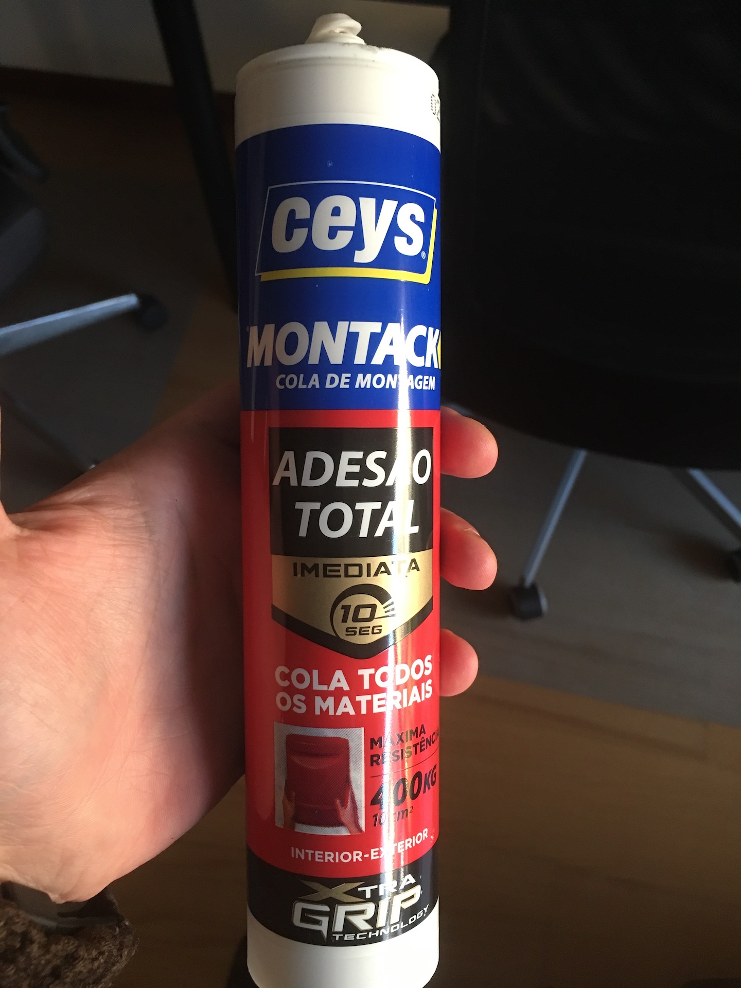
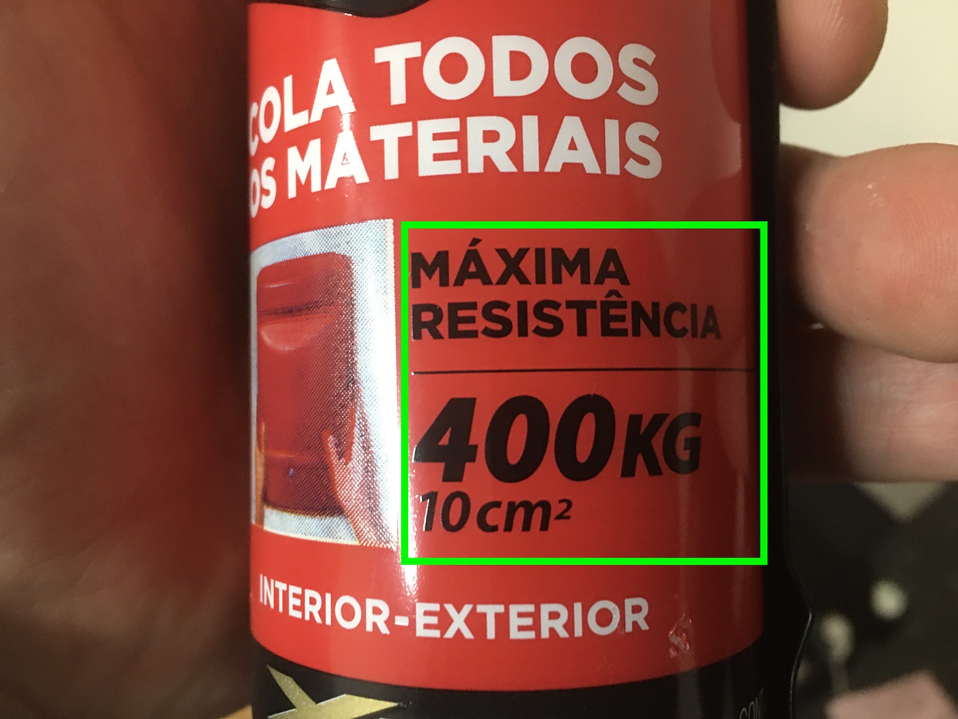
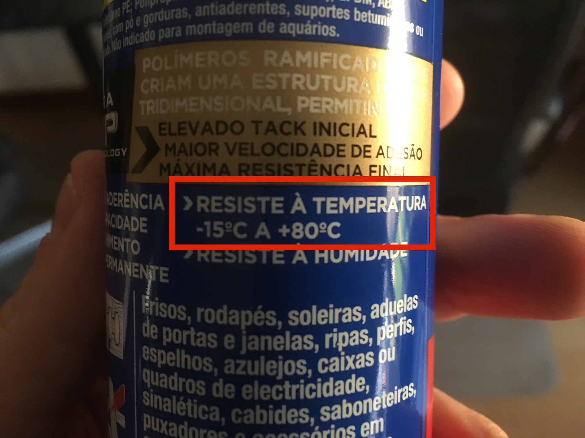 Brand, Strength rating and Temperature range of my adhesive
Apply it using the adhesive gun:
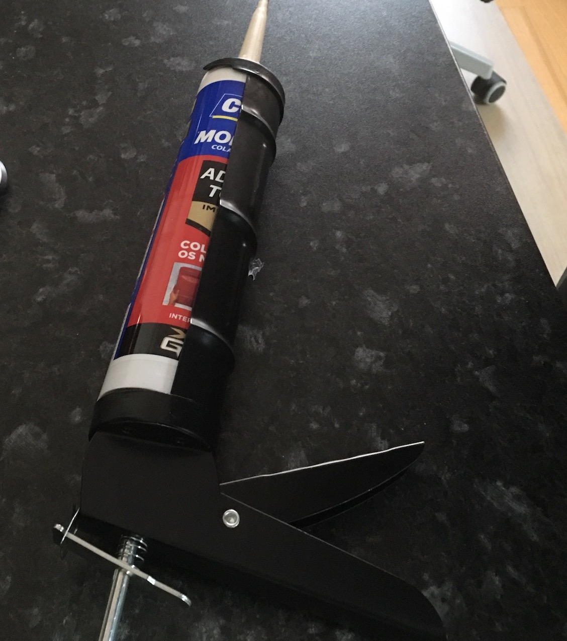 Adhesive gun
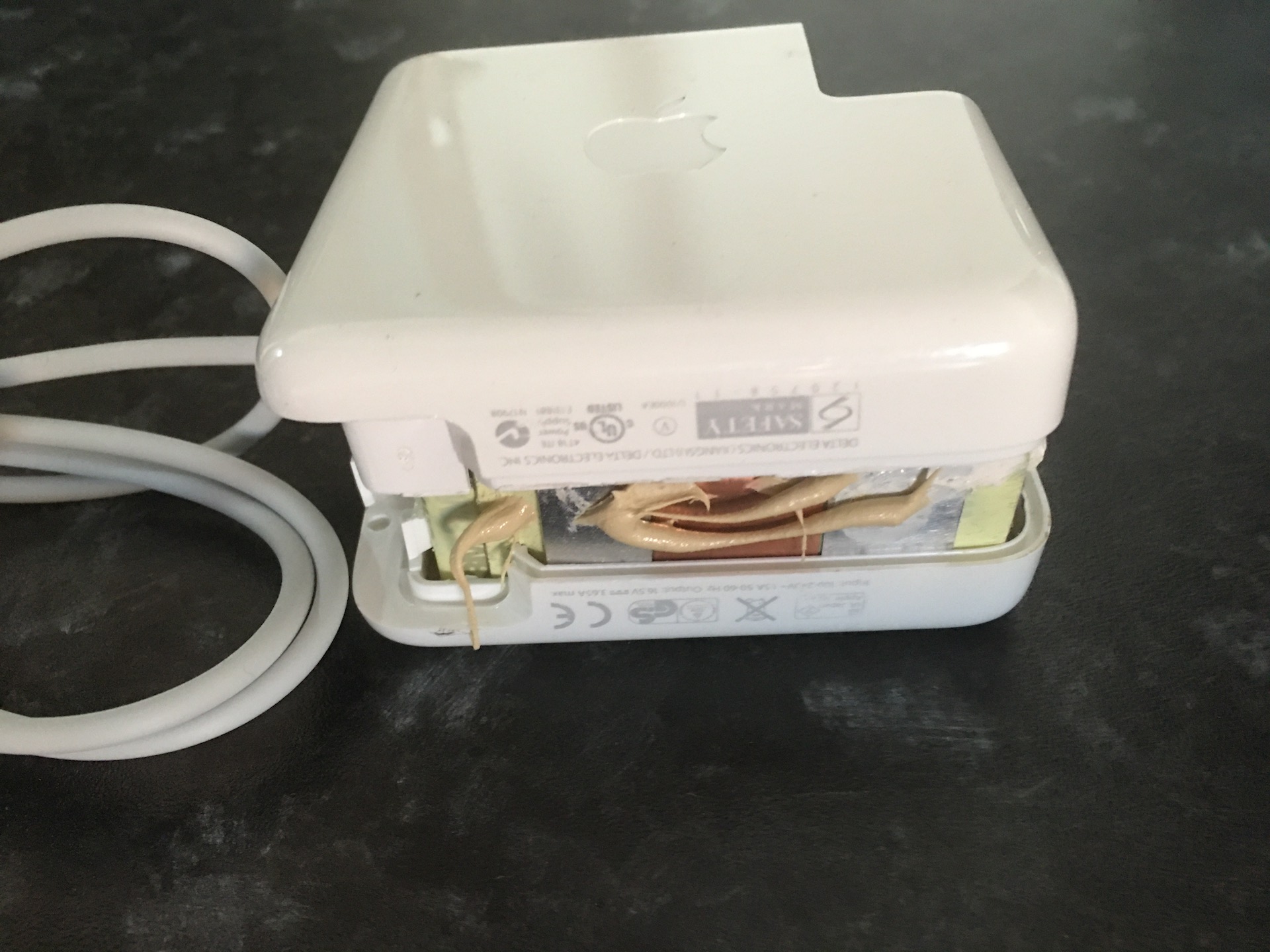
Align the two halves and apply some more adhesive to the outside edge.
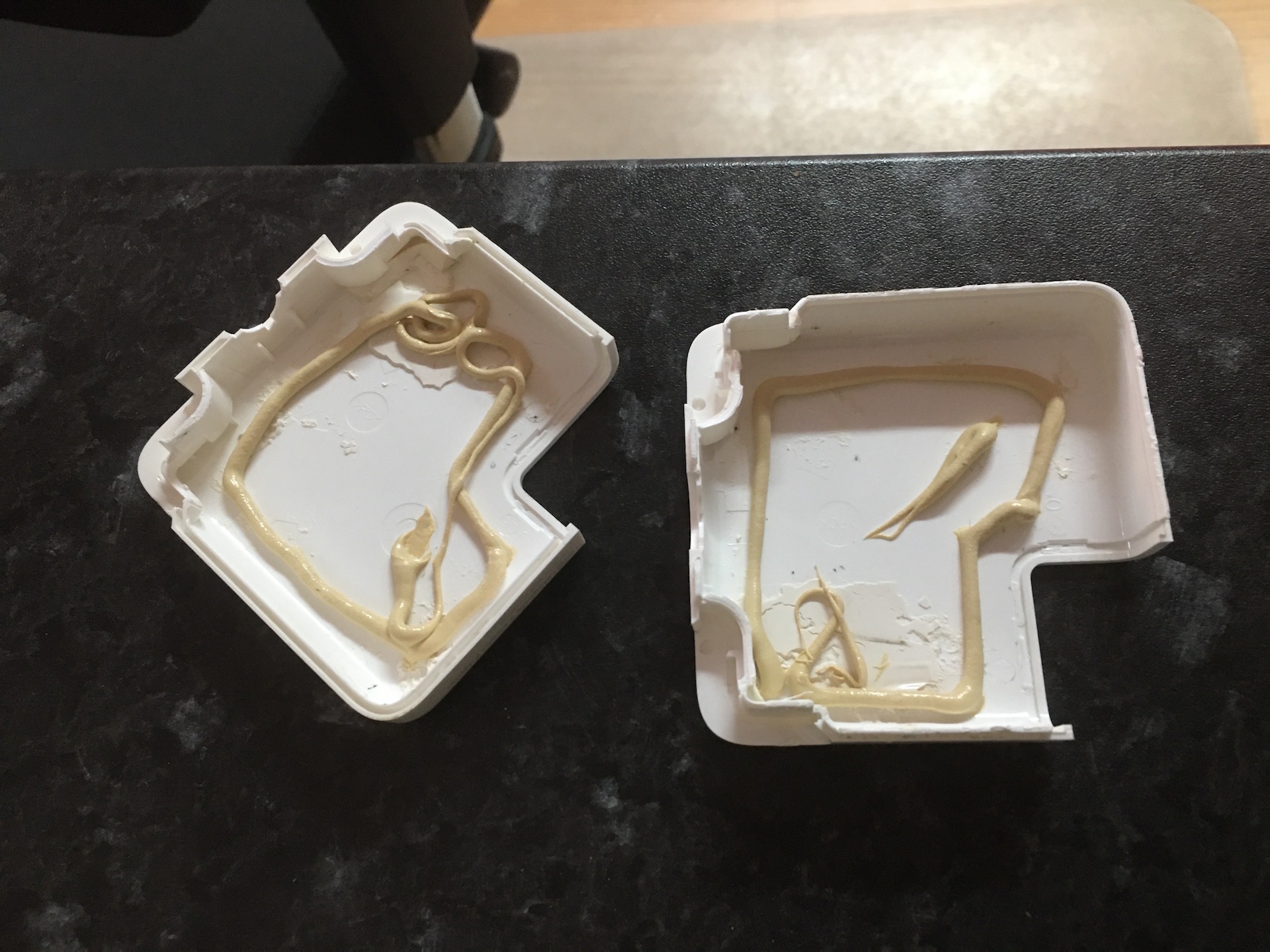
 Apply adhesive to the inside of the charger’s two plastic halves.
Wipe off the excess adhesive that can come out the sides before you let it dry.
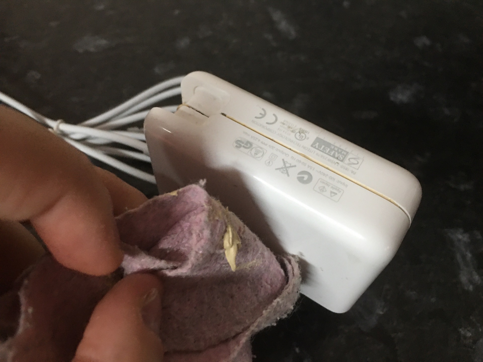 Applying adhesive to the edge of the charger
Press the charger securely in a vice for 72 hours for the adhesive to achieve maximum strength (not too much otherwise you will crush the fragile plastic). Place a rag around the charger so that the jaws of the vice do not damage the casing of the charger.
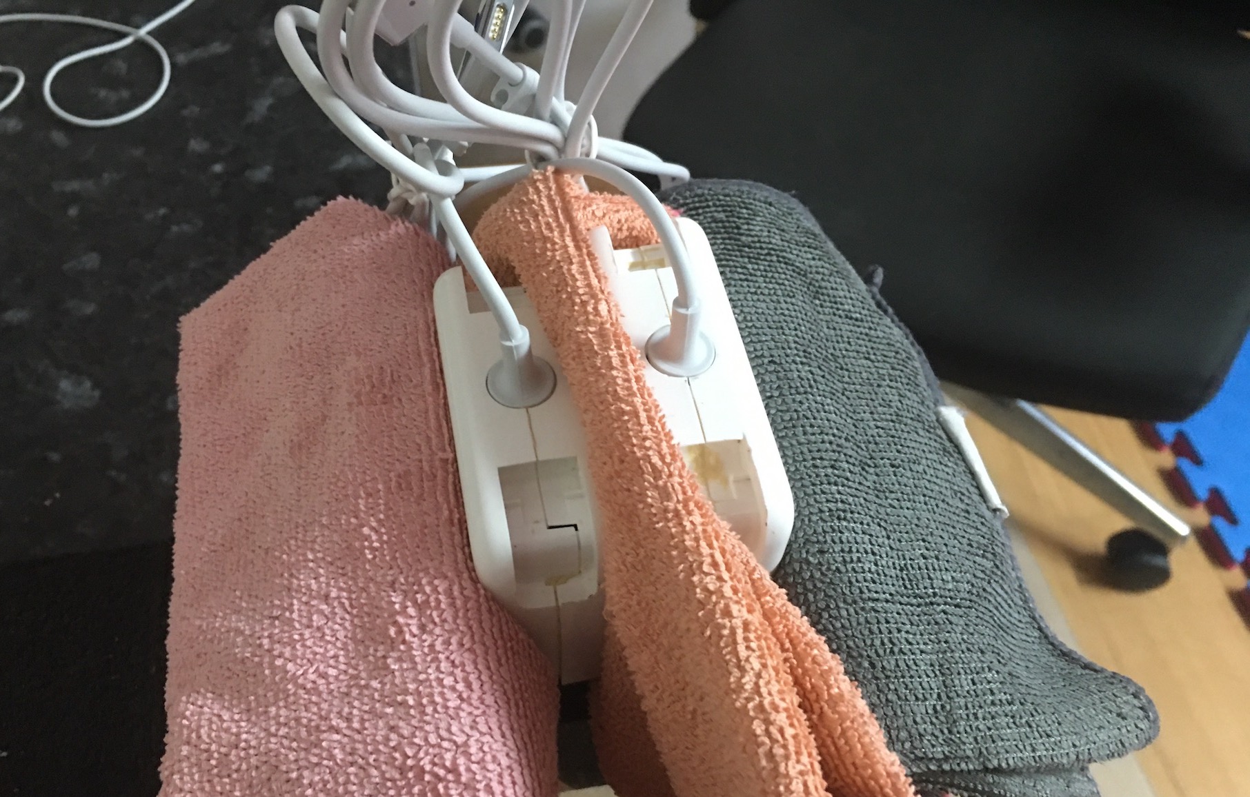 The MacBook charger, clamped in a vice for the adhesive to cure
Final result
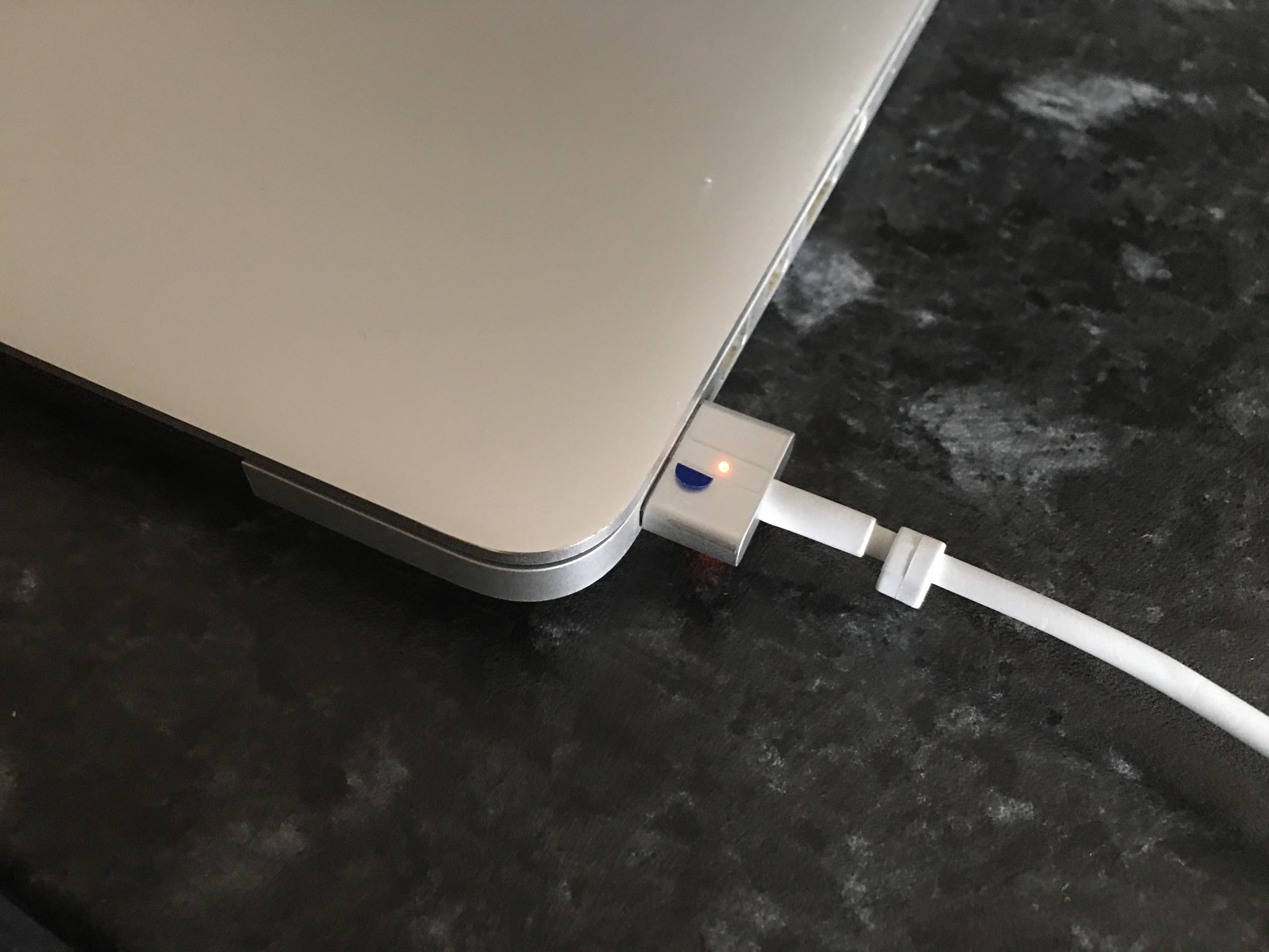 Final results! My MacBook is charging its battery again!
Comments
Post comment